Frame the flight regime
Defined the forward-flight and transition constraints around low dynamic pressure, disturbed inflow, cruise speed and the fixed span envelope.
Case study 01 · Aircraft design · Aerodynamics
Aerodynamic development of a 1:6-scale tilt-rotor demonstrator, balancing lift, stability, structural depth and propulsor integration inside a strict 2.2 m span envelope.
The engineering problem
The aircraft had to transfer lift from distributed rotor thrust to wing-borne flight while remaining controllable through disturbed propeller inflow. A 2.2 m span limit, 60 kg target MTOW and 20 m/s cruise condition forced aerodynamic efficiency, low-speed handling, internal volume and structural depth into the same design trade.
I led the aerodynamics team across configuration trade studies, airfoil selection, wing and tail sizing, low-order analysis and CFD evidence. I produced the preliminary aerodynamics design report and helped turn analysis outputs into a configuration that could pass review and move toward manufacture.
Engineering approach
Defined the forward-flight and transition constraints around low dynamic pressure, disturbed inflow, cruise speed and the fixed span envelope.
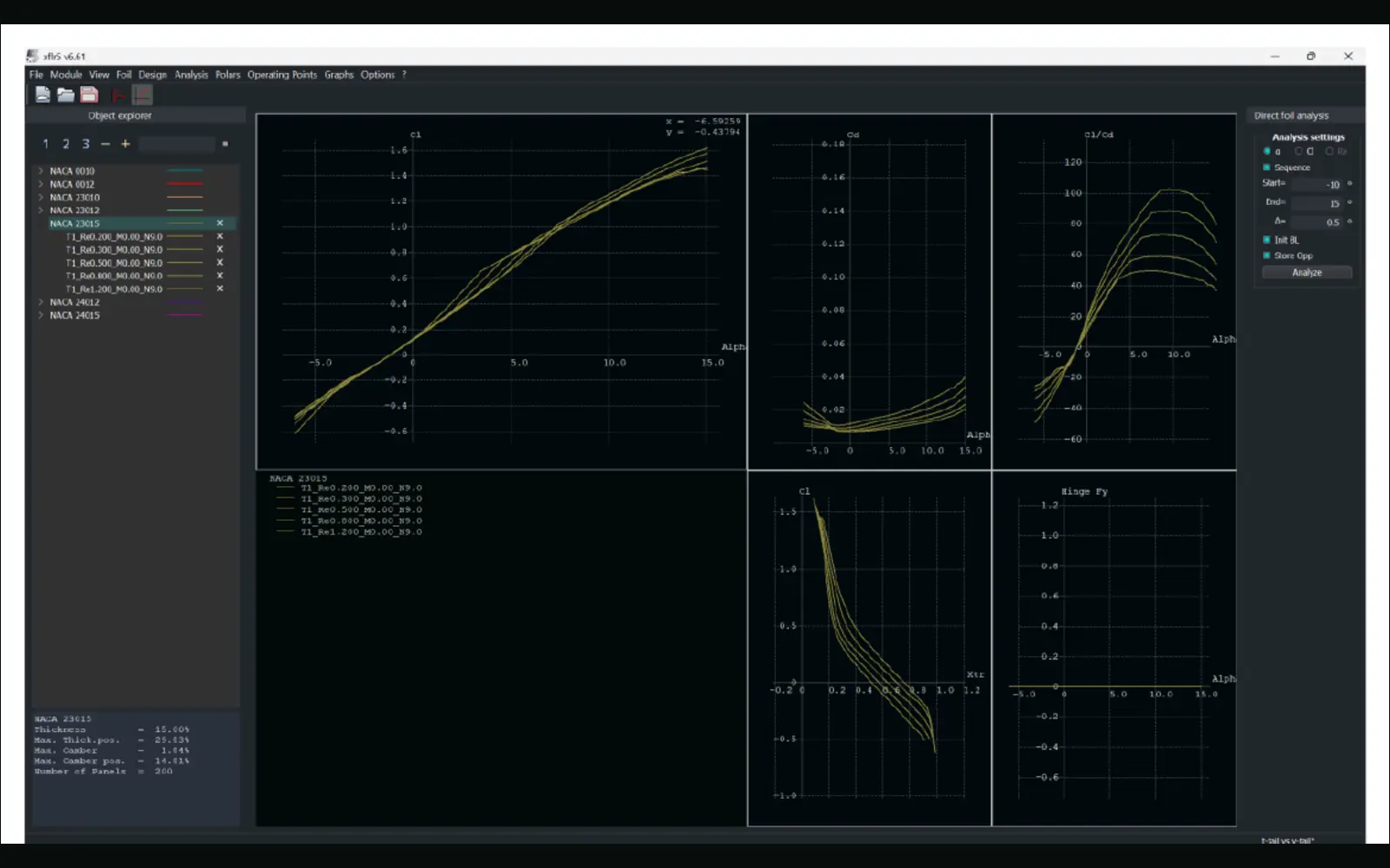
Compared low-Reynolds-number behaviour and selected NACA 23015 for lift capability, progressive stall and 15% structural thickness.
Progressed a tapered 0.770 m² wing with -2° washout and a V-tail sized around pitch-yaw authority, clearance and structural practicality.
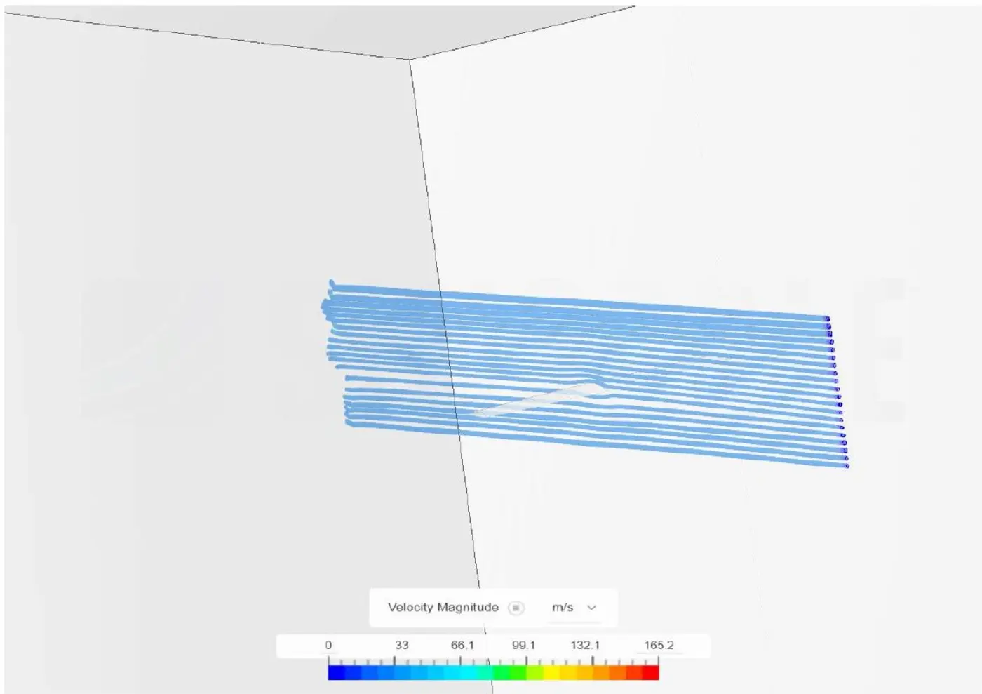
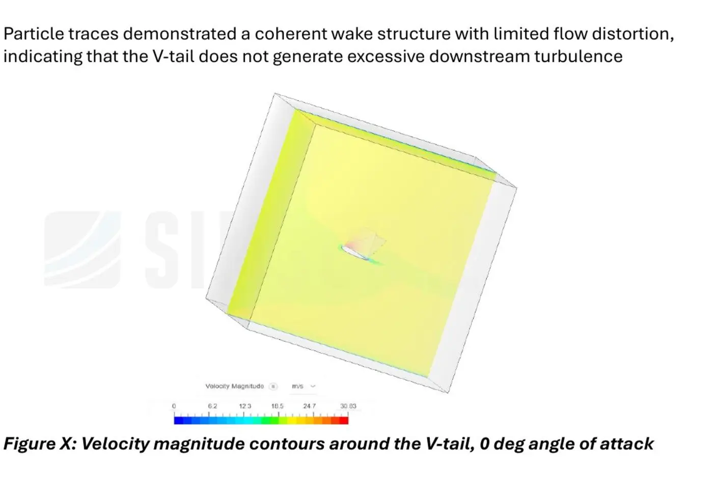
Connected XFLR5 lifting-line and polar studies with SimScale k-ω SST flow visualisation at representative cruise conditions.
Decision record
| Design decision | Evidence used | Trade-off accepted |
|---|---|---|
| NACA 23015 main wing section | Low-Reynolds-number polar comparison supported its lift capability, progressive stall behaviour and 15% thickness for structural depth. | Accepted a thicker section and its profile-drag cost to protect structure, buildability and low-speed margin. |
| -2° geometric washout | XFLR5 comparison indicated approximately 12% lower tip loading and moved predicted stall onset from 11° to 12.5°. | Accepted a modest departure from the ideal lift distribution to favour root-first stall and retain aileron authority. |
| Tapered wing inside the 2.2 m span | A 0.770 m² wing with aspect ratio 6.29 balanced the lift requirement with the fixed span, rotor packaging and structural envelope. | Aerodynamic efficiency remained constrained by the demonstrator's integration and manufacturing limits. |
| Compact V-tail configuration | Sizing and CFD flow visualisation balanced pitch-yaw authority, clearance and integration with the wider aircraft layout. | Coupled controls and propeller-inflow effects still required higher-fidelity validation before design freeze. |
Technical evidence
Source documentation
These collaborative project documents substantiate the design-review trail. The case study above identifies my individual responsibility within the wider team effort.
Limitations
The review-stage drag model used simplified assumptions and did not fully resolve viscous interference or propeller-slipstream interaction. The CFD evidence was primarily qualitative, so it supported flow interpretation rather than final force and moment certification.
Next engineering step
I would run integrated propeller-wing CFD across the transition corridor, complete a mesh-independence study, and validate lift, drag and pitching moment with force-balance wind-tunnel testing before freezing propulsion and battery margins.
Methods & tools
Continue exploring
Team URSA launch vehicle