Trade the fin configuration
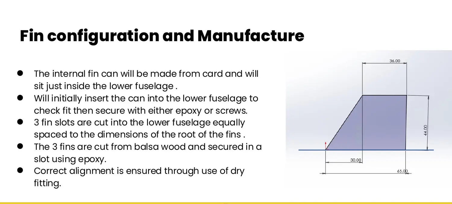
Compared rectangular, tapered and swept planforms, then evaluated three versus four fins around stability, drag, mass and manufacturability.
Case study 02 · Launch vehicle · Structures & design
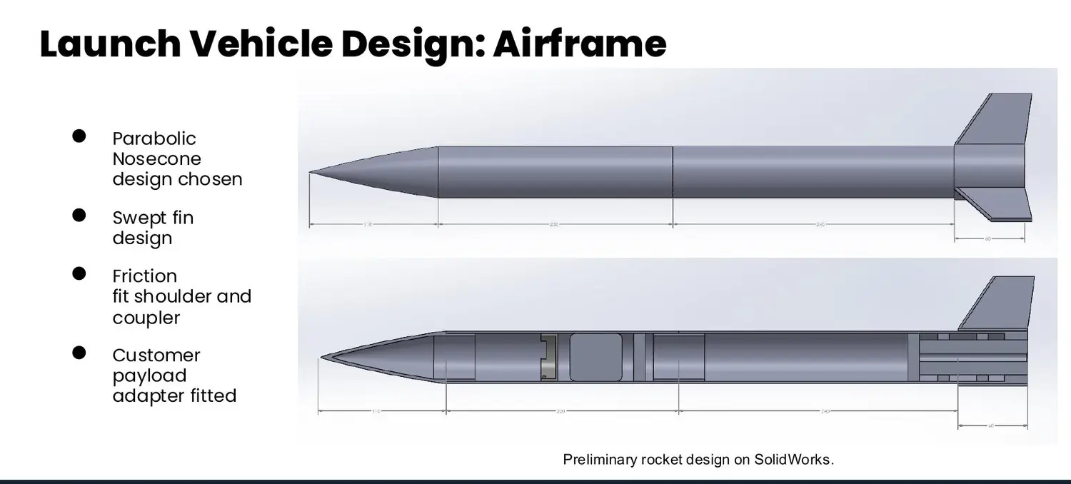
Airframe and fin development for the UKSEDS National Rocketry Championship, translating stability, load, manufacturing and integration constraints into a reviewable launch-vehicle design.
The engineering problem
Team URSA had to approach a 2,200 ft target apogee while carrying customer and rideshare payloads, preserving a safe stability margin and supporting reliable recovery. Changes made for manufacture and integration affected mass, drag, stability and altitude together.
Within the airframe team, I contributed to fin planform and material trades, airframe geometry, stability modelling and manufacturing/test planning. The work linked SolidWorks geometry and OpenRocket results to decisions that could be reviewed, built and verified.
Engineering approach
Compared rectangular, tapered and swept planforms, then evaluated three versus four fins around stability, drag, mass and manufacturability.
Used SolidWorks geometry with OpenRocket flight and stability modelling to expose the consequences of each configuration update.
Planned a repeatable fin-can integration route using controlled slots, dry fitting, alignment checks and resin reinforcement.
Mapped axial and transverse fin-load tests, airframe stiffness checks and recovery tests to competition requirements and safety factors.
Decision record
| Design decision | Evidence used | Trade-off accepted |
|---|---|---|
| Three swept fins | Rectangular, tapered and swept planforms—and three- versus four-fin layouts—were compared through stability, drag, mass and manufacturing criteria. | Lower drag and mass placed more importance on accurate fin alignment and repeatable manufacture. |
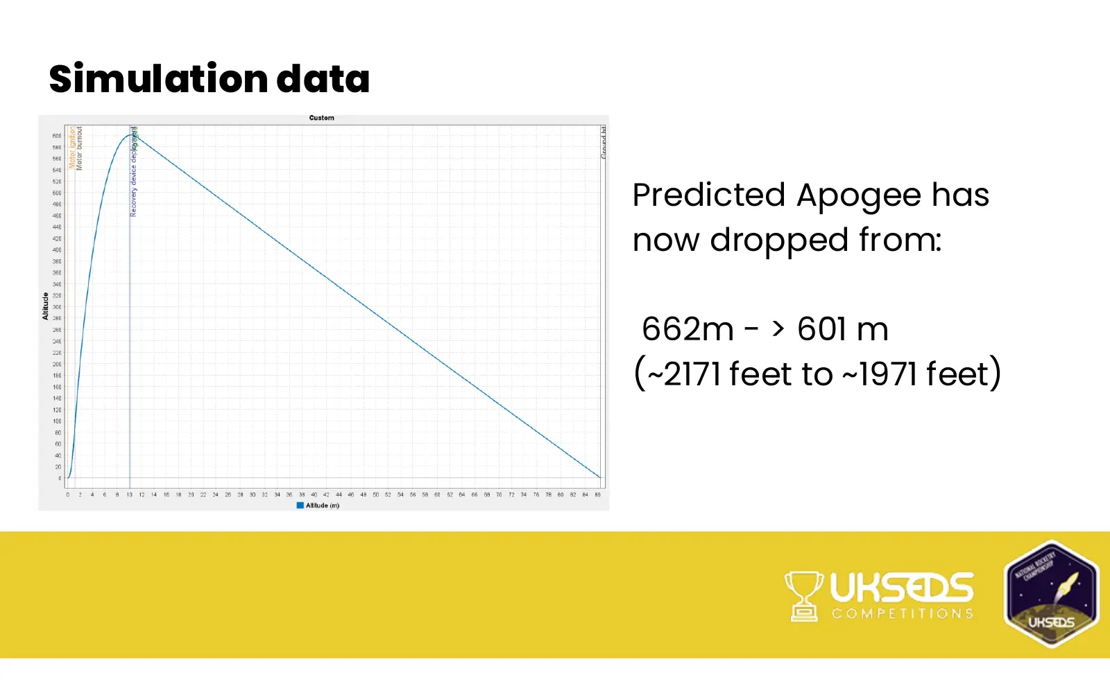
| 50 mm × 590 mm airframe update | The revised model brought stability into the 1.75–2.5-calibre band while reducing predicted apogee from about 2,171 ft to 1,971 ft. | Improved stability and integration were prioritised despite an approximately 200 ft performance penalty. |
| Slotted, reinforced fin-can assembly | Controlled slots, dry fitting, alignment checks and resin reinforcement formed a repeatable manufacturing route. | The stronger, more controllable joint added process steps and resin mass that needed to be managed. |
| Physical verification before flight | Axial and transverse fin-load tests, airframe stiffness checks and recovery tests were mapped to the review requirements. | Additional schedule and test effort was required to close uncertainty left by trajectory and CAD models. |
Technical evidence
Source documentation
These collaborative project documents substantiate the design-review trail. The case study above identifies my individual responsibility within the wider team effort.
Preliminary design review
Critical design review
Manufacturing review
Limitations
At the documented review stage, physical structural and recovery tests had not yet been completed. OpenRocket could expose trajectory and stability trends, but final mass properties, surface finish and as-built alignment still carried uncertainty.
Next engineering step
I would close the apogee gap through measured as-built mass properties, surface-finish and fin-geometry refinement, then rerun the wind envelope before completing fin-load, motor-mount and recovery deployment tests.
Methods & tools
Continue exploring
Aetheris-6 eVTOL aerodynamics